Description
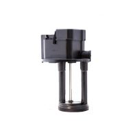
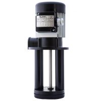
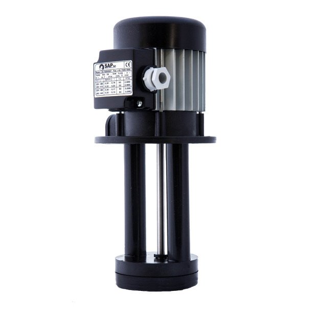
 The PA-35 is a motor-driven pump for machine tools. It is suitable for larger, semi-automatic and fully automatic band saws, as well as for smaller lathes and milling machines, surface grinders, automatic drilling machines, thread cutting machines etc.
The PA-35 is designed for industrial use and is characterized by its robustness and long service life. It is operated with three-phase current (alternatively single-phase operation in the PA-35M version) and meets the requirements of IP 54 (learn how IP-codes correspond with NEMA).
The housing is made of extruded aluminum or non-flammable, acid-resistant plastic in accordance with the following standards: VDE 0730 and UL 94. The pump shaft is made of V-2A steel, the bearings are from NSK, extremely durable and vibration-damped, mounted in semi-rigid shells, which leads to an almost vibration-free operation.
The pump is resistant to liquids permeated with particles (e.g. contaminated coolant) and all chemical compounds that are typically used in cooling lubricants. It can be throttled up to 80%, which enables optimal adjustment of the flow rate. The inlet port of the pump is compatible with Quick-Fit couplings.
We can customize the PA-35 for all mains voltages upon customer request.
Specifications
Power Consumption: 90 Watt
Voltages: 230 V | 400 V
Phases: 1 or 3 Phases
Frequency: 50 Hz
Discharge Head: 13.8 feet
Capacity: 9.5 GPM (36 l/Min)
Immersion Depths: 3.3 in (85 mm) – 11.8 in (300 mm)
Cover Material: Extruded aluminium, POM
Impeller Material: POM
Shaft Material: stainless steel (AISI 303)
Bearings: CW long-life bearings in semi-rigid supports
Weight: 3.1 lb
Outlet Thread Ø: 3/8 ” or 1/2 ”
Protection Category: NEMA 3 (IP 54)
SKU: 6120
Discharge Head & Capacity
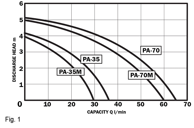
Figure 1 shows the maximum delivery rate depending on the discharge head for the pump types PA-35 and PA-70. Note that the optional single-phase variant (type “PA-35M” or “PA-70M”) has about 10% less power.
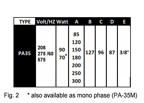
Figure 2 shows the length of the immersion tube under “A”, which must be taken into account when ordering, see also Figure 3.
Installation and Electrical Connection
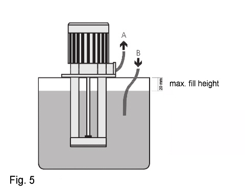
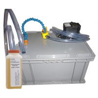
The pump is to be installed on the tank as shown in Figure 5 so that the immersion tube is immersed in the coolant. The housing part that contains the electric motor must not come into contact with the coolant. Ensure that there is adequate overflow in the tank.

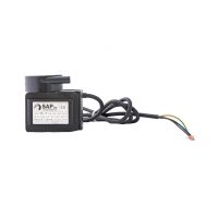
Figure 6 shows the connection of the pump in star or delta connection. As an alternative to this standard, we can also convert the pump to single phase operation without incurring additional costs. Please note that approximately 10% of the pump’s capacity is lost.